Add only what the part needs
Useful for complex geometry, internal channels, personalisation and low-volume production.
 THE FAST 3D PRINTGet a quotation →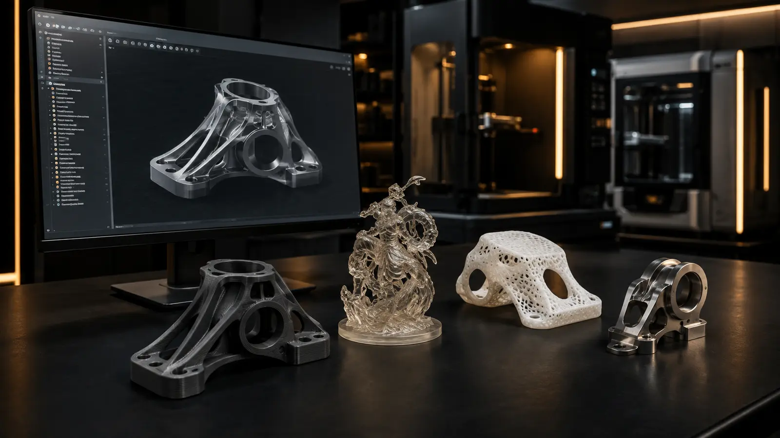
A complete buyer's guide—from technology and materials to files, pricing, quality and requesting a production quotation.
3D Printing, or Additive Manufacturing, creates a physical object from digital data by adding material one layer at a time. This is fundamentally different from machining, which removes material by cutting, milling, drilling or turning.
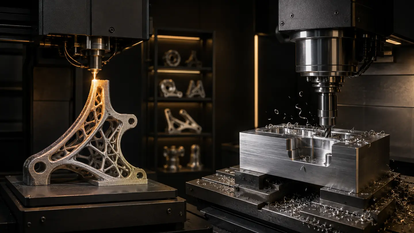
Useful for complex geometry, internal channels, personalisation and low-volume production.
Excellent for many precise conventional geometries, but tool access and material waste must be considered.
The two methods do not need to compete. Many industrial projects use a hybrid workflow: additive manufacturing for speed and geometric freedom, then CNC machining or finishing for critical surfaces and tolerances.
FROM DIGITAL FILE TO PHYSICAL PART
Different machines use different energy sources and materials, but an industrial workflow normally follows seven connected stages.
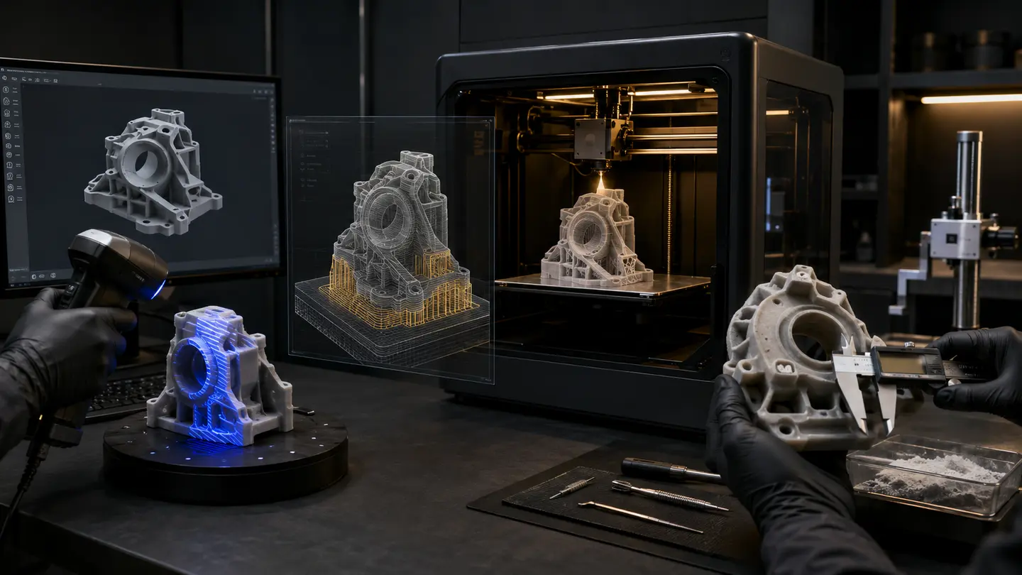
Create the geometry in CAD or capture a physical part with 3D scanning and reverse engineering.
Export a production-ready STL, 3MF or another format appropriate to the workflow.
Set layer height, orientation, supports, infill and process parameters in the slicer.
The prepared toolpath controls motion, energy, temperature and material delivery.
The machine adds or cures material continuously until the complete geometry is formed.
Remove supports, wash, cure, sand, coat, polish or heat-treat as required by the process.
Check dimensions, surfaces and functional requirements before the part is approved.
A thinner layer generally reveals finer surface detail but increases production time. The right setting depends on geometry, material, part size and the surface that will be visible or functional.
THE RIGHT PROCESS FOR THE RIGHT PART
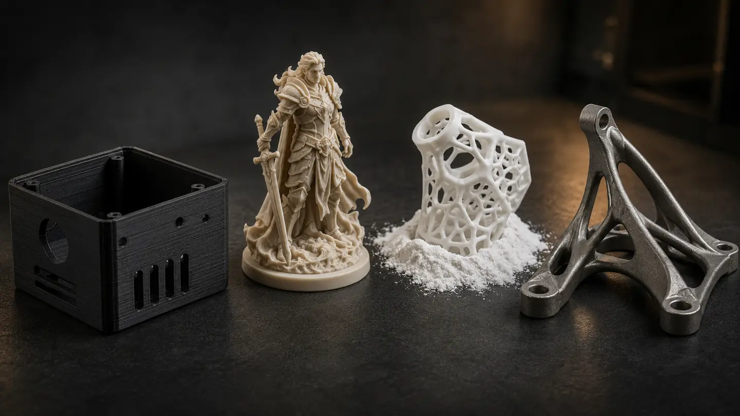
Cost-effective prototypes, enclosures, jigs and large parts.
Fine-detail models, sacred art, jewellery masters and dental work.
Strong functional parts and complex forms without conventional supports.
Consistent batches of functional parts with efficient production speed.
High-performance, lightweight and internally complex metal components.
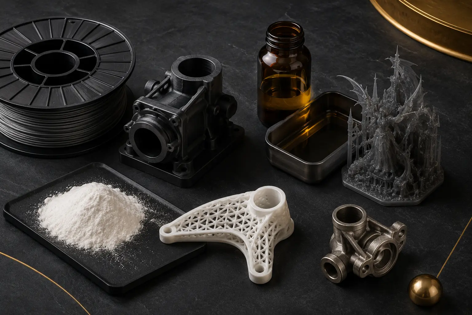
MATERIALS DEFINE PERFORMANCE
PLA · PETG · ABS · ASA · TPU · Nylon · Carbon/Glass-fibre reinforced
Wide cost range, large sizes and many mechanical behaviours.Standard · Tough · Castable · Dental · Engineering
Selected when fine detail, smooth surfaces or application-specific resin performance is important.PA11 · PA12 · TPU · Metal powders
Supports complex functional geometry and efficient batch nesting.SELECTION CHECKLIST
Visual model, fit check, mould master or end-use part?
Identify critical dimensions and surfaces before selecting resolution.
Strength, flexibility, temperature, chemicals and outdoor exposure.
One large prototype and a batch of 100 functional parts need different economics.
Plan supports, sanding, painting, polishing, coating or casting from the start.
Compare preparation, printing, finishing, inspection and lead time—not machine price alone.
DESIGN FOR ADDITIVE MANUFACTURING
DfAM means designing around the strengths and limits of a layer-based process rather than copying a part designed for machining or moulding. It can improve performance while reducing material, assembly and support.
Use self-supporting angles and choose orientation before finalising geometry.
Lattice and topology optimisation remove material where it contributes little.
Reduce fasteners, interfaces and assembly steps where maintenance allows.
Create conformal cooling or fluid paths that conventional tools cannot reach.
Good DfAM also includes drainage, powder removal, inspection access, tolerances, joining and post-processing—not geometry alone.
QUALITY, STANDARDS & SMART MANUFACTURING
Industrial adoption requires common terminology, design rules, digital-data control and repeatable inspection. Frequently referenced frameworks include ISO/ASTM 52900 for AM fundamentals and terminology, ISO/ASTM 52910 for design guidance and the ASTM F42 standards programme.
Generate and compare geometries against weight, strength and process constraints.
Keep material only along the load paths that matter.
Store validated files and produce parts when needed.
Create patient-, user- or product-specific variants without dedicated tooling.
Combine printing with CNC, coating, casting or inspection.
Use material efficiently and produce closer to the point of need.
FROM PROTOTYPE TO PRODUCTION
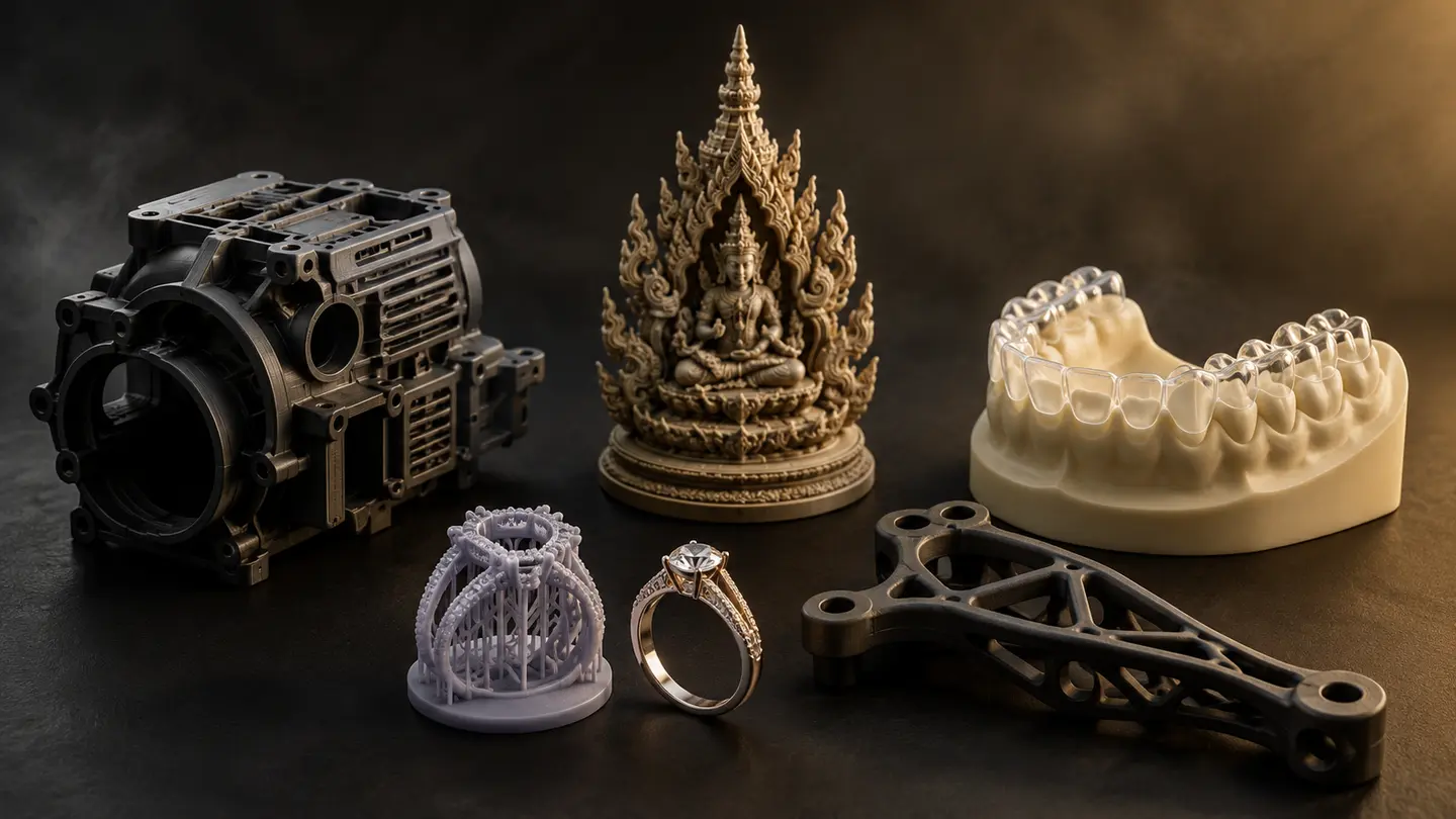
WHEN ADDITIVE MANUFACTURING MAKES SENSE
3D printing is often most valuable before production volume is high enough to justify dedicated tooling, when geometry changes frequently, or when delay is more expensive than the part itself. A fair comparison includes design preparation, tooling, minimum order quantity, lead time, revision cost, inventory, finishing and inspection.
Check size, fit, ergonomics and assembly while design changes are still inexpensive.
Produce a small batch for the market, a pilot line or a specialist application.
Internal channels, lightweight lattices and customised interfaces can justify the process.
Validated spare-part files can be produced when needed, subject to material and quality controls.
Very high volumes, simple geometry, extremely tight conventional tolerances or a mandatory certified material may favour moulding, machining or a hybrid route. The objective is the best production decision—not using 3D printing everywhere.
FILES, ORIENTATION & QUALITY
STL stores a triangulated surface and normally carries no reliable unit, colour or material data. OBJ can include richer surface information, while 3MF can preserve units and more manufacturing metadata. For controlled engineering work, retain the original CAD file and revision alongside the production mesh.
Mesh resolution must be high enough to preserve curves without creating an unnecessarily large file. Before production, inspect for holes, inverted normals, self-intersections, non-manifold edges and shells that are not joined. Then agree which dimensions are critical and how they will be measured after post-processing.
State millimetres or another unit explicitly and include one known reference dimension.
Every intended solid must form a closed, valid volume before slicing.
Mark fits, threads, sealing faces, thin details and surfaces that must remain visible.
Balance strength, supports, surface marks, accuracy and production time.
Allow material for sanding, machining, coating, painting, polishing or casting.
Agree dimensions, surface, colour, fit test and sample approval before production.
3D PRINTING SERVICE BUYER GUIDE
People searching for a 3D printing service, rapid prototype, resin print, FDM part or 3D print price are often comparing quotations that do not include the same scope. Price per gram alone cannot represent file repair, orientation, supports, failed-build risk, finishing, inspection or delivery. A useful quotation begins with a clear production brief.
Attach STEP/STL/OBJ or clear photographs, units, overall size and revision.
State whether it is a visual model, fit prototype, casting master, jig or end-use part.
Loads, heat, UV, moisture, chemicals and required flexibility guide material selection.
Mark critical dimensions, visible surfaces, colour, finish, fit test and sample approval.
If you have no 3D file, a physical part can begin with 3D scanning and reverse engineering, while an idea or reference image can begin with 3D modelling. For metal outcomes, the project may combine a printed master with mould-making or investment casting. The right supplier should compare the complete route rather than forcing every job into one machine.
Geometry, dimensions, material, layer height, orientation, support, quantity, finish, inspection, machine occupancy and deadline all affect total cost. Send the same brief to every supplier before comparing price.
FREQUENTLY ASKED QUESTIONS
They are closely related. Additive Manufacturing is the broader industrial term covering design, material control, production, finishing and quality assurance.
Choose FDM for cost-effective functional or larger parts. Choose resin when fine detail and smooth surfaces are the priority. Final selection still depends on strength, environment and finishing.
Yes, when the process, material, orientation, tolerances and inspection plan match the application. It is not limited to visual prototypes.
STL and 3MF are common print formats, while STEP is useful for engineering review and OBJ can retain colour or texture information. A photo or physical sample can also be used to start scanning or modelling.
A successful part begins with clear requirements. Share the model, photo, dimensions, quantity and intended use so the production team can compare process, material, finishing and total cost before printing begins.
Discuss your 3D project →